PLAXIS 3D
3D Geotechnical Engineering Software
Flexible Geotechnical Analysis Software
Trusted Geotechnical Finite Element Analysis Software
Perform advanced finite element or limit equilibrium analysis of soil and rock deformation and stability, as well as soil structure interaction, groundwater, and heat flow.
PLAXIS 3D
The most basic PLAXIS 3D option to perform everyday deformation and safety analysis for soil and rock.
PLAXIS 3D Advanced
Get everything in PLAXIS 3D, plus enhances your design capabilities with advanced features and material models for creep or flow-deformation coupling.
Includes:
• PLAXIS 3D
• Creep or flow-deformation coupling
• Consolidation analysis
• Steady state groundwater
PLAXIS 3D Ultimate
Extend the capabilities of PLAXIS 3D Advanced
Includes:
• PLAXIS 3D Advanced
• Analyze the effects of vibrations
• Simulate hydrological, time-dependent variations of water-levels, or flow functions
PLAXIS 3D WorkSuite
Most comprehensive!
Includes:
• PLAXIS 3D Ultimate
• PLAXIS Designer
• PLAXIS 3D LE for limit equilibrium slope stability analysis
Eliminate The Complexity. Choose PLAXIS.
WHAT IS PLAXIS 3D?
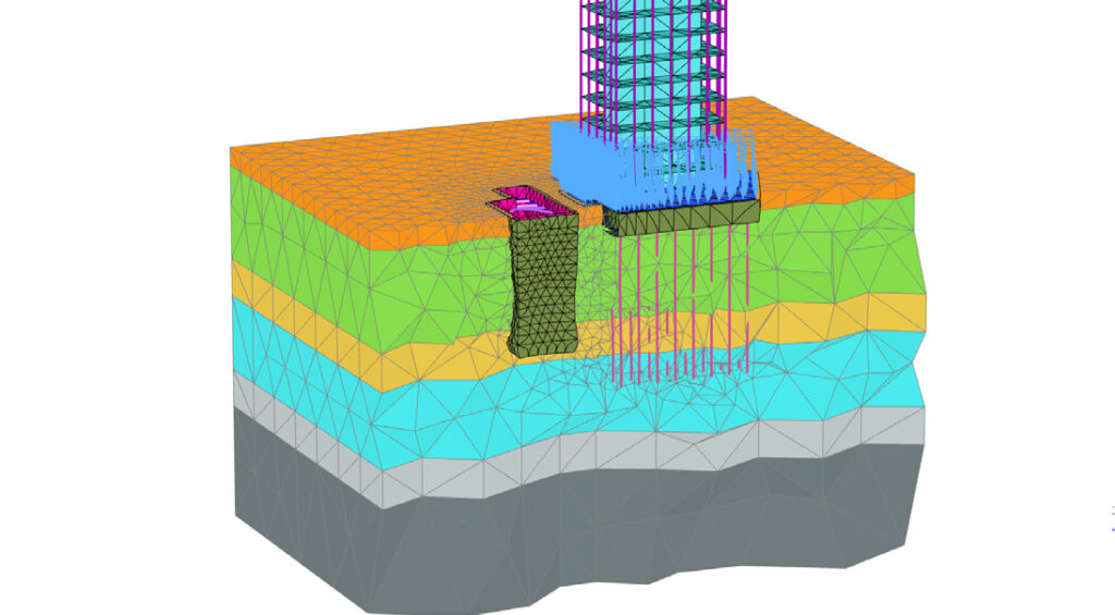
PLAXIS 3D includes the most essential functionality to perform everyday deformation and safety analysis for soil and rock. This comprehensive software for the design and analysis of soils, rocks, and associated structures makes it easy to model in full 3D.
Reliably solve infrastructure challenges
Easily generate and scale construction sequences for excavations. Facilitate steady-state groundwater flow calculations, including flow-related material parameters, boundary conditions, drains, and wells. Use interfaces and embedded pile elements to model movement between soil and foundation, such as slipping and gapping. Get trustworthy results with realistic soil models and a complete portfolio of visualization abilities.
Get realistic assessments of stresses and displacements
To meet the unique geotechnical challenges of soil structure interactions, PLAXIS 3D offers different calculation types, such as Plastic, consolidation, and safety analysis. A range of material models for predicting the behavior of various soils and rock types, combined with robust calculations, helps ensure reliable results. You can display these forces in various ways and use cross-section applications to inspect certain areas in greater detail.
Drive efficiency with multidiscipline workflows
Create logical geotechnical digital workflows that take projects from subsurface imports through design and analysis to various outputs.
WHAT IS PLAXIS 3D ADVANCED?
PLAXIS 3D Advanced includes everything that is included in PLAXIS 3D, plus it further enhances your geotechnical design capabilities with more advanced features and material models. You can consider creep or flow-deformation coupling through consolidation analysis. Additionally, you can solve your problems faster than PLAXIS 3D with the multicore solver.
WHAT IS PLAXIS 3D ULTIMATE?
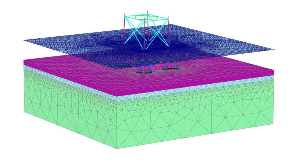
PLAXIS 3D Ultimate extends the capabilities of PLAXIS 3D Advanced so you can analyze the effects of vibrations in the soil, like earthquakes and moving traffic loads. You can also simulate complex hydrological conditions through time-dependent variations of water levels or flow functions on model boundaries, as well as soil boundaries.
3D Geotechnical Dynamic Modeling
PLAXIS 3D Ultimate is an easy-to-use software that is suited for more advanced seismic analysis. When you need something that goes beyond the low-frequency vibrations, this is the choice for you. You can:
- Analyze the effects of human-made or natural seismic vibrations in soil
- Perform analyses on the effects of vibrations in the soil from earthquakes, pile driving, vehicle movement, heavy machinery, or train travel
- Accurately calculate the effects of vibrations with a dynamics analysis when the frequency of the dynamic load is higher than the natural frequency of the medium
- Perform a ground response analysis and liquefaction analysis using the UBCSand model
3D Geotechnical Groundwater Flow
Go beyond the default options of steady-state groundwater flow analysis of PLAXIS with PLAXIS 3D Ultimate.
- Simulate the unsaturated, time-dependent, and anisotropic behavior of soil
- Simultaneously calculate changes in pore pressures and deformation by performing a fully-coupled flow-deformation analysis
- Use the Flow-only mode to exclude displacements and stresses from the calculation if you are only interested in groundwater flow, making it easier to use.
WHAT IS PLAXIS 3D WORKSUITE?
PLAXIS 3D WorkSuite includes everything that you get with PLAXIS 3D Ultimate, plus you get PLAXIS 3D LE, and PLAXIS Designer.
PLAXIS 3D LE
With PLAXIS 3D LE you can model and analyze geo-engineering projects for limit equilibrium slope stability analysis and perform finite element analysis of groundwater seepage in unsaturated or saturated soils.
PLAXIS Designer
PLAXIS Designer is excellent for building 3D conceptual models to overcome the challenges of merging and analyzing data. With Bentley’s open modeling environment, PLAXIS Designer allows you to visualize and manipulate geotechnical data including topology, boreholes, piezometers, and other field instrumentation data, as well as engineering staged construction and design.
PLAXIS 3D At-A-Glance
As infrastructure assets are crucially linked to subsurface environments, they are vulnerable to geotechnical risk. Risk in complex geotechnical engineering and rock mechanics projects can be mitigated by performing 3D analysis of deformation and stability. Make safe, cost-efficient decisions and reduce risk by employing PLAXIS 3D, the comprehensive solution for design and analysis of soils, rocks, and associated structures, developed by geotechnical leaders with over 50 years of experience.
FAST AND EFFICIENT FINITE ELEMENT MODEL CREATION
Finite element modeling in full 3D is easy with drawing tools such as extrude, intersect, combine, and array operations. Utilize multiple boreholes to quickly create the subsurface model then add structural elements like plates, discontinuities, piles, and prescribed loads or displacements. For tunnel solutions, a designer wizard offers quick creation of tunnel cross-sections, reinforcements, tunnel lining, and loading conditions. Meshing features automatic and manual mesh refinements, automatic generation of irregular, regular or swept meshes, and capabilities to inspect the mesh quality. It is also possible to import geometry from CAD files, or fully automate model generation by using Python-based scripting.
REALISTIC ASSESSMENT OF STRESSES AND DISPLACEMENTS
Accurately model the construction process by (de)activating soil/rock clusters and structural elements in each calculation phase in Staged construction mode. Perform the relevant geotechnical analysis by selecting between plastic, safety, and consolidation analysis as well as dynamic or fully coupled flow-deformation analysis. Employ various
constitutive models ranging from simple linear to advanced highly nonlinear models that allow accurate simulation of most soil and rock types. Well-proven and robust calculation procedures ensure that calculations converge and provide accurate results for the most
common or complex models, excelling in settlement, groundwater flow or dynamic analysis.
POWERFUL AND VERSATILE POST PROCESSING
The versatile Output program offers various ways to display forces, displacements, stresses, velocities, accelerations, temperature, and flow data shown in contour, vector, and iso-surface plots. Cross-section capabilities allow areas of interest to be inspected in more detail, and data can be copied from tables for further postprocessing in other software. The curve manager enables the creation of graphs that can plot various results across a selection of calculation phases. Python scripting allows Output results to be used in connected external applications or automated modeling workflows in the PLAXIS ecosystem.


TECHNICAL CAPABILITIES
• Automatic Swept Meshing for more efficient meshes
• Elastoplasticity for beams and plates
• Connections
• Design arbitrary geometries using Combine, Intersect, Extrude,
• Loft, Blendsurfaces and Revolve around axis tools
• CAD Import and Export*
• Nonlinear geogrids: Elastoplastic (N-ε) and Viscoelastic (time-dependent)
• Discontinuity element to model fractured or jointed rocks
• Polar and rectangular array
• Tunnel Designer with easy definition of rock bolts, umbrella arches and girders*
• Define excavation sequence in the Tunnel Designer*
• Automatic generation of staged construction phases for tunnels*
• Automate processes with full command line support and remote scripting API*
* Some features are dependent on product level or SELECT® entitlement.
• Industry standard soil models: Hardening Soil, HSSmall, Soft Soil and Soft Soil Creep
• Rock models: Jointed rock, Hoek-Brown with parameter guide, N2PC rock creep model with MC failure criterion
• Concrete
• UDCAM-S with cyclic accumulation and optimization tool
• NGI-ADP
• User-defined soil models*
• Static and dynamic liquefaction models: NorSand, UBCSand
* Some features are dependent on product level or SELECT® entitlement.
• Well-proven and robust calculation procedures
• Multicore computing and 64 bit
• K0, gravity loading and field stress for initial stress calculations
• Distinguish between a plastic calculation, safety or consolidation analysis
• Facilities for steady-state or transient groundwater flow calculations, including flow-related material parameters, boundary conditions, drains, and wells
• Pseudo-static and dynamic analysis, including dynamics with consolidation and free field and compliant base boundary conditions, and moving point or line loads
• Specify load, acceleration or head variations through time with linear, harmonic, or table functions
• Fully coupled flow-deformation analysis
• Convenient and intuitive phase explorer
• Automatic regeneration of construction stages for geometric changes
* Some features are dependent on product level or SELECT® entitlement.
• Realistic assessment of stresses and displacements
• Vector, contour, and iso-surfaces plots of displacement, stress, pore pressure, or acceleration
• Structural forces from cylindrical and square volume piles
• Curves Manager to create loads vs. displacement, Pseudospectral acceleration plots or cross-section curves
• Advanced data slicing
• Movable cross-sections
• Extensive report and movie generator
• PLAXIS 3D Viewer
* Some features are dependent on product level or SELECT® entitlement.
• Surface settlements and mechanical response of intact, fractured or jointed rock masses due to tunneling, mining, or reservoir depletion
• Slope stability and seepage analysis for earth and tailing dams, embankments, and open pit mines
• Predicting differential settlements of buildings adjacent to excavation pits
• Stability of and seepage into excavation pits, and lateral displacements of diaphragm walls
• Calculate consolidation time for pore pressure dissipation in undrained loading problems
• Bearing capacity and foundation settlement analysis for high-rise buildings, LNG tanks, and other structures (for example offshore suction anchors)
• Liquefaction analysis to predict the safety of critical infrastructure like levees or large dams under earthquake
• Stability of embankments for high-speed railways
• Seismic design of jetties, quays, walls, building foundations
• Stability of dams or levees under rapid drawdown, during seasonal variations of water level or during precipitation or flooding
* Some features are dependent on product level or SELECT® entitlement.
• Provides a universal ID to link together all activity within
• Bentley applications
• Manage license entitlements at a user level, without requiring activation keys or hardware dongles
• Access personal learn material, paths, and history, timely product related news, automatic product updates, and notifications
FREQUENTLY ASKED QUESTIONS
PLAXIS is an easy-to-use, finite element software application that helps with the analysis of subsurface environments for geoengineering projects.
PLAXIS is a computer application that performs finite element analyses (FEA) within the realm of geotechnical engineering, including deformation, stability and water flow. The name PLAXIS comes from PLastic and AXISymmetry, indicating the geometric types handled in the original code of the software application.
By applying interface elements PLAXIS users can simulate the interaction between a structure and soil. While without an interface no relative displacement (slipping/gapping) will be possible between structure and soil.
When interface applied, node pairs will be created at the interface of structure and soil. Each node pair consists of two nodes – one belongs to the structure and the other belongs to the soil. The interaction between these two nodes consists of two elastic-perfectly plastic springs. One elastic-perfectly plastic spring to model the gap displacement and one elastic-perfectly plastic spring to model slip displacement.
Seequent, The Bentley Subsurface Company | Seequent is the subsurface software company within Bentley Systems. Together, we’re helping build a more resilient future by connecting the built world above ground with the hidden world below it. It’s easy to purchase a Virtuoso Subscription, through Bentley’s eStore, and still get the expert technical support from Seequent’s subsurface experts.
Processor
Required: Dual Core CPU
Recommended: Quad Core CPU
Operating System
Windows 10, Windows 11
Memory
Recommended: minimum 8 GB
Large projects may require more
Disk Space
Minimum 2 GB free space on the partition where the WindowsTEMP directory resides, and 2 GB free space on the partition where projects are saved. Large projects may require significantly more space on both partitions.
For best performance, ensure that the TEMP directory and the project directory reside on the same partition.
Display
Graphics Card
Required: GPU with 256 MB OpenGL 3.3 Bentley strongly recommends avoiding simple onboard graphics chips in favor of a discrete GPU from the nVidia GeForce or Quadro range with at least 128-bit bus and 1 GB of RAM, or equivalent solution from ATI/AMD.
Video
Required: 1024 x 768 pixels 32-bit color palette, Recommended: 1920 x 1080 pixels 32-bit color palette
For the most up-to-date system requirements, visit Bentley Communities.

